P
Pressure Loss
Every meter of pipe, valve, fitting and elbow generates pressure losses. As velocity increases, these losses increase significantly.

Lessons learned from industrial gases, LNG and cryogenic applications
In industrial gas facilities, LNG installations, cryogenic storage systems and bulk gas distribution networks, operators frequently face the same challenge:
"We need more flow."
The immediate reaction is often to install a larger pump or compressor. While increasing equipment size seems like the logical solution, the true limitation is frequently much simpler: the piping system itself.
No matter how large a pump is installed, the fluid can only flow through the available cross-sectional area of the piping. If the suction line, withdrawal line, or process piping is undersized, the system may already be operating at its hydraulic limit.
In many cases, the true bottleneck is not the machine. It is the pipe connected to it.
 Cryogenic tank and piping
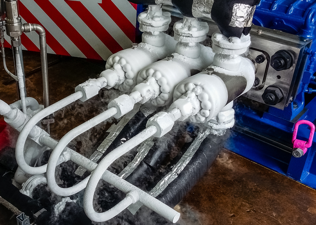 Cryogenic pump manifold
A common misconception in industrial facilities is that additional flow can always be achieved by increasing pump capacity.
However, if the suction piping is undersized, the system quickly reaches its hydraulic limitations.
Flow capacity is governed not only by equipment but by the entire hydraulic network.
Increasing pump size while leaving piping unchanged often creates additional pressure losses, higher velocities and unstable operation without delivering the expected flow increase.
The full flow path must be reviewed for restrictions. A smaller valve, check valve, strainer, reducer, flow meter, flexible connection or any other line equipment can become the controlling limitation even when the main pipe size appears acceptable.
The tank outlet nozzle also needs to be properly sized. If the nozzle is smaller than the downstream line, the system may still behave like an undersized piping system.
Pipe layout also matters. Angles, bends and routing choices influence pressure losses and stability, but this topic deserves its own detailed engineering article.
Every meter of pipe, valve, fitting and elbow generates pressure losses. As velocity increases, these losses increase significantly.
Insufficient pressure at the pump inlet may lead to vapor bubble formation and collapse, damaging internal components.
A pump can only deliver what the piping system is capable of supplying.
Poor suction conditions often result in vibration, noise and unreliable operation.
During project development, engineers often focus on pressure, temperature and equipment sizing.
Velocity is sometimes checked much later.
Yet fluid velocity has a direct influence on:
A simple velocity verification performed early can prevent expensive modifications later in the project lifecycle.
Excessive velocity increases dynamic forces transmitted into the piping system.
Rapid changes in liquid flow can create damaging pressure waves commonly known as water hammer.
High velocity accelerates component wear at elbows, valves, reducers and restrictions.
Pumps, valves and instrumentation experience increased stress and reduced service life.
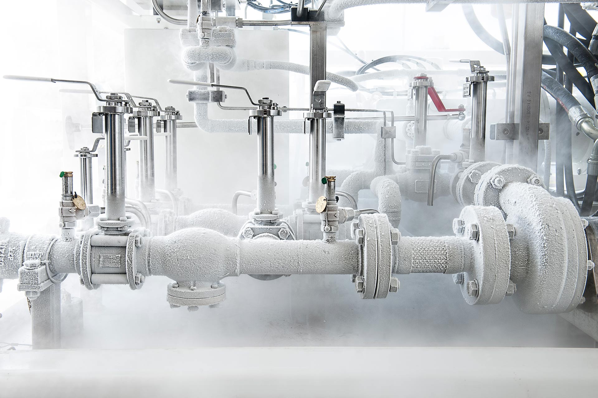 Cryogenic pump and pipework
Gas systems introduce additional challenges due to compressibility.
Excessive gas velocity may lead to:
In many industrial gas facilities, noise becomes the first indication that velocity limits have been exceeded.
Oxygen systems require particular attention.
Unlike inert gases, oxygen can present additional risks related to localized heating and ignition mechanisms.
High velocities combined with pressure changes may contribute to adiabatic compression effects and localized temperature increases.
Good engineering practice typically applies more conservative velocity limits for oxygen service and follows recognized oxygen-clean design standards.
The earlier velocity calculations are performed, the easier and less expensive it is to optimize a piping system.
Replacing a pipe during design is simple.
Replacing a pipe after construction can become extremely costly.
To support engineers during concept development, troubleshooting and optimization studies, EDGE-GAS has developed a Fluid Velocity Calculator.
The calculator helps engineers quickly evaluate expected velocities in:

Actual EDGE-GAS Fluid Velocity Calculator print screen showing a larger-pipe recommendation for liquid nitrogen service.
“Sometimes the problem is not the pump.
It is the pipe.”
Many flow limitation issues originate not from equipment selection but from piping design decisions made early in a project.
Understanding fluid velocity is one of the simplest and most effective methods for identifying future bottlenecks before they become operational problems.
Those checks should include not only the nominal pipe diameter, but also valves, check valves, reducers, instruments, filters, tank outlet nozzles and any other restriction installed in the flow path.
At EDGE-GAS, we developed our Fluid Velocity Calculator based on practical lessons learned from industrial gas, LNG and cryogenic projects worldwide.
A few minutes spent checking velocity today may prevent costly modifications tomorrow.
Lessons learned from industrial gases, LNG and cryogenic applications
In industrial gas facilities, LNG installations, cryogenic storage systems and bulk gas distribution networks, operators frequently face the same challenge:
"We need more flow."
The immediate reaction is often to install a larger pump or compressor. While increasing equipment size seems like the logical solution, the true limitation is frequently much simpler: the piping system itself.
No matter how large a pump is installed, the fluid can only flow through the available cross-sectional area of the piping. If the suction line, withdrawal line, or process piping is undersized, the system may already be operating at its hydraulic limit.
In many cases, the true bottleneck is not the machine. It is the pipe connected to it.
Cryogenic tank and piping
Cryogenic pump manifold
A common misconception in industrial facilities is that additional flow can always be achieved by increasing pump capacity.
However, if the suction piping is undersized, the system quickly reaches its hydraulic limitations.
Flow capacity is governed not only by equipment but by the entire hydraulic network.
Increasing pump size while leaving piping unchanged often creates additional pressure losses, higher velocities and unstable operation without delivering the expected flow increase.
The full flow path must be reviewed for restrictions. A smaller valve, check valve, strainer, reducer, flow meter, flexible connection or any other line equipment can become the controlling limitation even when the main pipe size appears acceptable.
The tank outlet nozzle also needs to be properly sized. If the nozzle is smaller than the downstream line, the system may still behave like an undersized piping system.
Pipe layout also matters. Angles, bends and routing choices influence pressure losses and stability, but this topic deserves its own detailed engineering article.
Every meter of pipe, valve, fitting and elbow generates pressure losses. As velocity increases, these losses increase significantly.
Insufficient pressure at the pump inlet may lead to vapor bubble formation and collapse, damaging internal components.
A pump can only deliver what the piping system is capable of supplying.
Poor suction conditions often result in vibration, noise and unreliable operation.
During project development, engineers often focus on pressure, temperature and equipment sizing.
Velocity is sometimes checked much later.
Yet fluid velocity has a direct influence on:
A simple velocity verification performed early can prevent expensive modifications later in the project lifecycle.
Excessive velocity increases dynamic forces transmitted into the piping system.
Rapid changes in liquid flow can create damaging pressure waves commonly known as water hammer.
High velocity accelerates component wear at elbows, valves, reducers and restrictions.
Pumps, valves and instrumentation experience increased stress and reduced service life.
Cryogenic pump and pipework
Gas systems introduce additional challenges due to compressibility.
Excessive gas velocity may lead to:
In many industrial gas facilities, noise becomes the first indication that velocity limits have been exceeded.
Oxygen systems require particular attention.
Unlike inert gases, oxygen can present additional risks related to localized heating and ignition mechanisms.
High velocities combined with pressure changes may contribute to adiabatic compression effects and localized temperature increases.
Good engineering practice typically applies more conservative velocity limits for oxygen service and follows recognized oxygen-clean design standards.
The earlier velocity calculations are performed, the easier and less expensive it is to optimize a piping system.
Replacing a pipe during design is simple.
Replacing a pipe after construction can become extremely costly.
To support engineers during concept development, troubleshooting and optimization studies, EDGE-GAS has developed a Fluid Velocity Calculator.
The calculator helps engineers quickly evaluate expected velocities in:
Actual EDGE-GAS Fluid Velocity Calculator print screen showing a larger-pipe recommendation for liquid nitrogen service.
“Sometimes the problem is not the pump.
It is the pipe.”
Many flow limitation issues originate not from equipment selection but from piping design decisions made early in a project.
Understanding fluid velocity is one of the simplest and most effective methods for identifying future bottlenecks before they become operational problems.
Those checks should include not only the nominal pipe diameter, but also valves, check valves, reducers, instruments, filters, tank outlet nozzles and any other restriction installed in the flow path.
At EDGE-GAS, we developed our Fluid Velocity Calculator based on practical lessons learned from industrial gas, LNG and cryogenic projects worldwide.
A few minutes spent checking velocity today may prevent costly modifications tomorrow.